

How Ambient Temperature Shapes the Performance of High-Speed Semiconductor Fuses
2026-08-27
For engineers designing power conversion systems, the thermal environment is not a secondary variable—it is a primary design constraint. When protecting sensitive IGBTs, thyristors, and SiC modules, the 690V AC Ultra Rapid Semiconductor Protection Fuse must operate within precise thermal boundaries. Galaxy Fuse has engineered its ultra-rapid fuse line to address this exact challenge, yet many specifiers overlook the single most influential external factor: ambient temperature. This blog examines the derating mechanics, provides actionable tables, and answers the most frequently asked questions about thermal management for these critical components.
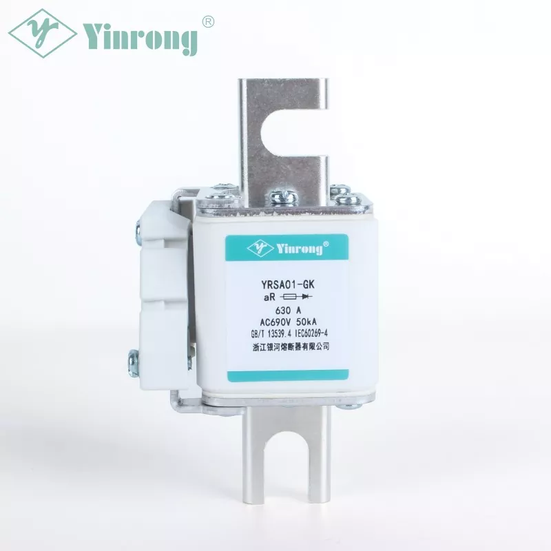
The Physics of Derating: Why Temperature Matters
A 690V AC Ultra Rapid Semiconductor Protection Fuse contains a calibrated fusible element, typically silver or copper alloy, designed to melt within milliseconds under fault currents. The melting time is inversely proportional to the square of the current (I²t), but this relationship assumes a reference ambient temperature—usually 25°C or 40°C, depending on the standard (IEC 60269 or UL 248).
As ambient temperature rises, three phenomena occur:
-
Increased baseline resistance – The element’s resistivity increases with temperature, raising the pre-arcing I²t.
-
Reduced heat dissipation – Convection and radiation from the fuse body decline when the surrounding air is hotter.
3 Lower melting energy threshold – The cumulative thermal energy required to reach the melting point decreases, meaning the fuse will trip earlier under the same load current.
Consequently, the continuous current-carrying capacity must be derated—reduced from the nominal rating—to prevent nuisance opening or premature aging.
Quantitative Derating Guidelines for 690V AC Ultra Rapid Fuses
The following table summarizes typical derating factors for Galaxy Fuse ultra-rapid semiconductor protection models (based on IEC 60269-4) at various ambient temperatures, assuming natural convection in still air and no additional heat sinks.
| Ambient Temperature (°C) | Derating Factor (Multiplier) | Recommended Max Continuous Load (% of In) |
|---|---|---|
| 25 (reference) | 1.00 | 100% |
| 40 | 0.95 | 95% |
| 50 | 0.90 | 90% |
| 60 | 0.85 | 85% |
| 70 | 0.78 | 78% |
| 85 (max operational) | 0.70 | 70% |
Example: A 690V AC Ultra Rapid Semiconductor Protection Fuse rated at 100A at 40°C should not carry more than 90A continuously when the enclosure ambient reaches 60°C.
Practical Installation Considerations
Beyond the raw numbers, engineers must evaluate:
-
Enclosure ventilation – Sealed cabinets may raise internal ambient by 15–25°C above room temperature.
-
Proximity to heat-generating components – Transformers, reactors, and braking resistors create localized hot spots.
-
Cyclic loading – Repeated near-rated currents generate cumulative thermal fatigue, accelerating element oxidation.
Galaxy Fuse recommends conducting a thermal mapping of the switchgear during worst-case operating conditions, then applying the derating factor from the table above. For installations exceeding 70°C continuous, forced-air cooling or a higher-rated fuse (e.g., 125A instead of 100A) becomes cost-effective.
Frequently Asked Questions (FAQ)
Q1: What is the reference ambient temperature for the derating curve of a 690V AC Ultra Rapid Semiconductor Protection Fuse, and how do I convert it if my installation uses a different baseline?
The reference temperature is typically 40°C for IEC-compliant fuses (including most Galaxy Fuse models) and 25°C for some UL-listed versions. To convert, you cannot simply shift the curve linearly. Instead, use the manufacturer’s published derating polynomial or table. For example, if your fuse is rated 100A at 40°C and your actual ambient is 55°C, locate the factor (0.90 for 50°C, interpolate to ~0.87 at 55°C) and multiply: 100A × 0.87 = 87A maximum continuous load. Always verify with the specific time-current curve provided for your exact part number, as element mass and filler material (quartz sand) affect thermal diffusivity.
Q2: Does a higher ambient temperature affect only the continuous current rating, or does it also change the short-circuit tripping characteristics (I²t and peak let-through) of a 690V AC Ultra Rapid Semiconductor Protection Fuse?
It affects both, but to different degrees. The continuous rating changes significantly (5–15% per 10°C rise). The short-circuit I²t and peak let-through current, however, are primarily governed by the fault magnitude and the fuse’s physical construction. At elevated ambients, the pre-arcing I²t decreases slightly (by about 3–5% at 70°C compared to 40°C) because the element starts closer to its melting point. The arcing I²t remains nearly constant because arc voltage depends on the filler and gap length, not on initial temperature. Therefore, for protection coordination (selectivity), you should still use the published I²t values at the reference temperature, but for overload protection, always apply the full derating factor.
Q3: How can I experimentally verify the correct derating for my specific enclosure when using a 690V AC Ultra Rapid Semiconductor Protection Fuse from Galaxy Fuse?
Conduct a temperature-rise test per IEC 60269-4 Annex A. Install the fuse in its actual holder, apply 80% of the rated current for at least 2 hours (until thermal equilibrium), and measure the temperature at the fuse terminals and the middle of the body using thermocouples. Compare the measured terminal temperature against the maximum allowable (usually 130°C for silver elements). If the terminal temperature exceeds 120°C at your intended load, reduce the current incrementally. Galaxy Fuse provides a free thermal simulation tool upon request, but field verification remains the gold standard. Document the stabilized temperatures at three load steps (50%, 75%, 100% of nominal) and plot your own derating curve for that specific cabinet design.
Summary Checklist for Design Engineers
-
Always start with the fuse’s datasheet reference ambient.
-
Measure real enclosure air temperature at the fuse holder, not at the cabinet inlet.
-
Apply derating from the table or manufacturer’s curve.
-
Recalculate coordination with upstream/downstream devices after derating.
-
For ambients above 70°C, consider a Galaxy Fuse model with a higher current rating or request a custom calibration.
Contact Us for Thermal Validation Support
Selecting the correct 690V AC Ultra Rapid Semiconductor Protection Fuse without accounting for ambient derating is a leading cause of field failures and unplanned downtime. Galaxy Fuse offers application engineering support, including thermal imaging verification, coordination studies, and sample testing under your actual load profiles. Reach out to our technical team with your enclosure drawings and load cycles—we will deliver a written derating recommendation within 48 hours. Visit our contact page or email us directly to schedule a consultation. Your system reliability is our priority.