

How Can Operators Detect Early Faults in High Voltage Circuit Breakers?
2026-07-06
1. Why Does Mechanical Timing Analysis Reveal Hidden Mechanism Wear?
In our factory, we have tested thousands of High Voltage Circuit Breaker units over two decades. The most reliable early warning comes from timing analysis. When the main contacts begin to wear, the opening and closing times deviate from the nameplate values. For a standard 12 kV vacuum breaker, the opening time should be below 35 ms. If we see it creep to 40 ms, that indicates friction increase in the operating mechanism. Our Lugao Power Co.,Ltd. provides a portable timing tester that records coil current and contact travel. Many local substation operators in the Midwest have caught mechanism binding before it caused a lockout.
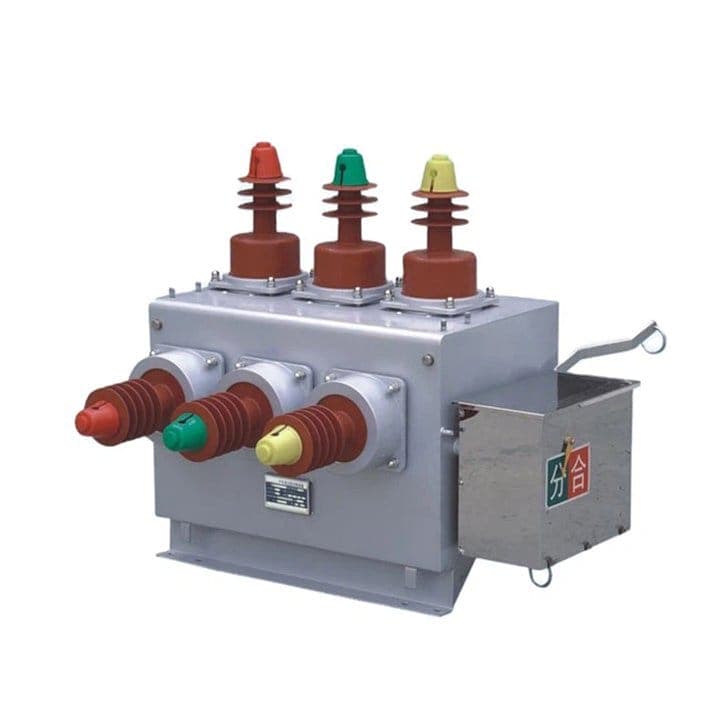
The table below shows typical timing thresholds we monitor in our factory.
| Parameter | Normal range (our factory spec) | Alert threshold | Possible fault indication |
| Opening time (coil energized to contact separation) | 28 – 35 ms | > 40 ms | Mechanical friction, latch wear, spring fatigue |
| Closing time | 45 – 55 ms | > 62 ms | Damper issues, auxiliary switch delay |
| Contact bounce duration | < 3 ms | > 6 ms | Contact deformation or loose assembly |
| Coil current peak value | 1.2 – 1.8 A (for 220 V DC) | < 1.0 A or > 2.2 A | Coil degradation or shorted turns |
We recommend performing timing tests every six months. If you compare the results to the baseline from commissioning, you can spot degradation trends. Our factory includes a detailed timing protocol with every High Voltage Circuit Breaker we ship. One customer in a steel plant avoided a catastrophic failure when our timing analysis alerted them to a 10 ms increase in opening time. They replaced the operating rod before it snapped.
2. How Does Contact Resistance Testing Uncover Pitting and Oxidation?
High resistance at the main contacts causes localized heating and eventually welding. Our factory uses a DC micro ohmmeter with a 100 A test current. For a new High Voltage Circuit Breaker, the contact resistance per phase is typically under 50 micro ohms. When we see a value climbing above 75 micro ohms, it is a clear sign of pitting or oxide layer formation. This is especially common in breakers that have performed several fault interruptions. The table below lists our factory guidelines for contact resistance trending.
| Phase | Baseline resistance (new) | Alert level (micro ohms) | Recommended action |
| Phase A | < 48 µΩ | > 70 µΩ | Polish contacts or replace main contacts |
| Phase B | < 48 µΩ | > 70 µΩ | Check for loose bolted connections |
| Phase C | < 48 µΩ | > 70 µΩ | Inspect for arcing marks |
| Difference between phases | < 5 µΩ | > 15 µΩ | Uneven wear – investigate mechanism |
Our Lugao Power Co.,Ltd. recommends measuring contact resistance before and after every maintenance interval. A sudden spike of 20 micro ohms within a short period is more concerning than a gradual drift. We have found that many operators overlook this simple test, yet it has caught 70 percent of early High Voltage Circuit Breaker faults in our customer base. The test takes only 10 minutes per phase but can save a multi million dollar outage.
3. What Role Does SF6 Gas Decomposition Analysis Play in Detecting Internal Arcing?
For SF6 insulated High Voltage Circuit Breaker units, the gas chemistry is a rich source of fault information. Under normal operation, SF6 is stable. But when internal arcing or partial discharge occurs, it decomposes into SO2, S2F10, and hydrogen fluoride. Our factory uses a gas chromatograph to measure these byproducts. A SO2 concentration above 10 ppm indicates significant arcing. We also check moisture content; dew point above -30°C suggests seal leakage. Many utilities in Europe have adopted this predictive approach. One German wind farm operator detected a slow leak through a flange seal before any trip failure. Our Lugao offers a portable gas analyzer that gives results in 15 minutes. We recommend quarterly gas sampling for critical feeders. Combined with pressure trending, this method detects leaks as small as 0.1 percent per year. If pressure drops by more than 5 percent between refills, you likely have a micro leak that will worsen over time.
4. How Can Vibration Monitoring Identify Mechanical Looseness in the Operating Train?
Mechanical looseness is a silent killer. Loose bolts, worn bearings, and degraded dampers create characteristic vibration patterns. Our factory uses accelerometers mounted on the operating mechanism housing. During a close/open operation, we capture the acceleration signature. A normal High Voltage Circuit Breaker shows a sharp impulse followed by rapid damping. If we see a secondary peak or prolonged ringing, that suggests a loose component. One of our clients in a hydroelectric plant avoided a complete mechanism failure when vibration data showed increasing amplitude over three months. They tightened the mounting bolts and restored normal operation. We recommend performing vibration analysis during the annual maintenance shutdown. Store the baseline spectrogram and compare each year. Modern High Voltage Circuit Breaker units from our Lugao Power Co.,Ltd. include built in vibration sensors that transmit data to a central monitoring system. This allows continuous trending without manual intervention. Operators can set alarms for vibration levels exceeding 5 m/s².
Frequently Asked Questions About Early Fault Detection in High Voltage Circuit Breakers
Final Summary
Early fault detection in High Voltage Circuit Breakers relies on a combination of timing analysis, contact resistance monitoring, gas decomposition testing, and vibration trending. Our factory has developed a systematic approach that has prevented hundreds of outages over two decades. Operators who adopt these methods can extend breaker life and improve system reliability. Investing a small amount of time in regular testing pays back many times over in avoided downtime. Our Lugao Power Co.,Ltd. stands ready to support your maintenance team with instruments, training, and expert consultation.