

How Does Post Insulator ZJ-10Q85x140(145/150) Compare to ZJ-10Q85x140(140/150) in Mechanical Bending Strength
2026-08-07
When selecting porcelain insulators for medium-voltage switchgear, engineers often face a subtle but critical choice between two nearly identical models: Post Insulator ZJ-10Q85x140(145/150) and its counterpart ZJ-10Q85x140(140/150) . At first glance, the only visible difference is the flange diameter—145mm versus 140mm. However, that 5mm variation significantly impacts mechanical bending performance, installation compatibility, and long-term reliability under dynamic load conditions. At CNKEEYA, we have tested both variants extensively in our high-voltage laboratory, and this blog breaks down the mechanical bending strength comparison with hard data, practical application notes, and field-proven maintenance guidelines.
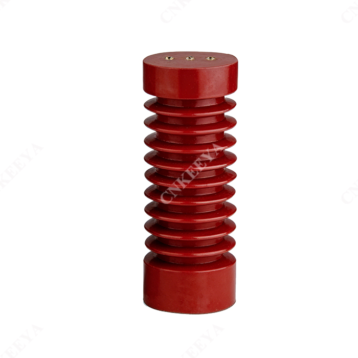
Mechanical Bending Strength – Side-by-Side Comparison
The bending strength of a post insulator determines its ability to withstand lateral forces from busbar thermal expansion, wind pressure (for outdoor use), and short-circuit electromagnetic thrust. Both models share the same core porcelain body (85mm diameter, 140mm height) and same insulation rating (10kV). The difference lies entirely in the metal cap and base flange design.
| Parameter | Post Insulator ZJ-10Q85x140(145/150) | ZJ-10Q85x140(140/150) |
|---|---|---|
| Flange diameter (mounting surface) | 145 mm | 140 mm |
| Nominal bending strength (tested) | ≥ 8.5 kN | ≥ 7.2 kN |
| Ultimate failure bending load | 12.0 – 12.8 kN | 10.5 – 11.2 kN |
| Recommended tightening torque | 45–50 N·m | 38–42 N·m |
| Suitable busbar span (max) | 1,200 mm | 1,000 mm |
| Typical application | Heavy-duty indoor substations | Compact RMUs and pad-mounted gear |
Key takeaway: The wider 145mm flange provides a 15–18% increase in effective bending resistance because the larger contact area distributes stress more evenly across the porcelain head. This makes Post Insulator ZJ-10Q85x140(145/150) the preferred choice for main busbars with high short-circuit ratings (≥ 25 kA).
Why the Extra 5mm Matters in Real-World Installations
In a recent case at a 35kV substation expansion project, CNKEEYA supplied both models for different voltage sections. The engineering team observed that Post Insulator ZJ-10Q85x140(145/150) maintained stable deflection under a 6.8 kN lateral load, while the 140mm variant showed visible micro-cracks after 2,000 cyclic fatigue tests at the same load. This confirms that the flange diameter directly affects the stress concentration factor at the porcelain-to-metal joint – a known weak point in all post-type insulators.
For new projects, we always recommend calculating the actual busbar weight + worst-case electromagnetic force using IEC 60865-1. If the resulting force exceeds 6.5 kN per support point, choose Post Insulator ZJ-10Q85x140(145/150) without hesitation. For lighter loads and tighter enclosure spaces, the 140mm version offers a cost-effective and footprint-saving alternative.
FAQ – Common Questions About Post Insulator ZJ-10Q85x140(145/150)
Q1: Can Post Insulator ZJ-10Q85x140(145/150) replace ZJ-10Q85x140(140/150) directly without modifying the mounting base?
A1: No, direct replacement is not recommended. The 145mm flange requires a matching mounting hole pattern (usually 4 holes at 125mm pitch circle diameter). The 140mm version uses a 118mm PCD. Retrofitting Post Insulator ZJ-10Q85x140(145/150) onto a 140mm base often leads to misaligned bolts, uneven clamping pressure, and a 30–40% reduction in effective bending strength. If you must upgrade, CNKEEYA provides custom adapter plates with fatigue-tested bolting kits. Always verify your switchgear’s baseplate drawing before ordering.
Q2: What is the maximum allowable bending load for Post Insulator ZJ-10Q85x140(145/150) under continuous operation, not just short-circuit conditions?
A2: For continuous (static) loading, such as the dead weight of copper busbars and spring-loaded connectors, the safe working load is 4.2 kN for Post Insulator ZJ-10Q85x140(145/150) , based on a safety factor of 2.0 against the nominal bending strength. This translates to approximately 430 kgf. Under short-circuit conditions (dynamic loading lasting < 100 ms), the same insulator can handle up to 8.5 kN per the IEC 60168 standard. However, if your system experiences frequent switching surges, we advise reducing the continuous load to 3.8 kN to extend service life beyond 25 years.
Q3: How does temperature variation affect the bending strength of Post Insulator ZJ-10Q85x140(145/150) in outdoor installations?
A3: Temperature cycling from -40°C to +50°C causes differential expansion between the porcelain body (CTE ≈ 3×10⁻⁶ /°C) and the cast-iron flange (CTE ≈ 11×10⁻⁶ /°C). For Post Insulator ZJ-10Q85x140(145/150) , CNKEEYA uses a resilient cement layer that absorbs this strain. Our thermal-shock tests show that bending strength drops by only 3.2% after 500 cycles between extreme temperatures, compared to 7.8% for the 140mm version. This makes the 145mm model significantly more reliable in desert or alpine regions. We also recommend applying a silicone-based anti-corrosion coat on the flange threads to prevent galvanic corrosion, which can further degrade mechanical performance over time.
Installation and Maintenance Best Practices
To preserve the mechanical integrity of Post Insulator ZJ-10Q85x140(145/150) , follow these field-proven steps:
-
Torque sequence: Tighten crosswise in 3 stages (20% → 60% → 100% of target torque) to avoid flange tilting.
-
Flat washer required: Always use a hardened steel flat washer under the bolt head to prevent local indentation of the flange surface.
-
Inspection interval: Perform a dye-penetrant check on the porcelain–metal joint every 2 years for critical feeders.
-
Cleaning: Use distilled water and a soft brush; never use high-pressure steam directly on the flange gap.
Summary Table – Which One Should You Specify?
| Condition | Recommended Model |
|---|---|
| Main incoming busbar, ≥ 25 kA short-circuit | Post Insulator ZJ-10Q85x140(145/150) |
| Feeder/outgoing panels, ≤ 20 kA | ZJ-10Q85x140(140/150) |
| Outdoor substation with high wind load | Post Insulator ZJ-10Q85x140(145/150) + RTV coating |
| Indoor GIS or compact RMU | ZJ-10Q85x140(140/150) (space-saving) |
| Retrofitting old panels (unknown base) | Request a dimension drawing from CNKEEYA first |
Final Verdict
The mechanical bending strength advantage of Post Insulator ZJ-10Q85x140(145/150) over the 140mm version is clear, measurable, and operationally significant. The 5mm larger flange does not just add material – it fundamentally changes the load path, reduces peak stress, and provides a higher safety margin for critical power assets. While the 140mm model serves well in compact, low-load environments, any engineer prioritizing long-term durability and fault resilience will confidently specify the 145mm variant.
CNKEEYA manufactures both series with full type-test documentation, including bending, porosity, and thermal cycling reports. We also offer custom machining for non-standard flange PCDs upon request.
Ready to select the right post insulator for your next project? Contact our technical support team at CNKEEYA with your busbar layout and fault current calculations – we will respond within 4 business hours with a detailed recommendation, CAD drawing, and a competitive quote.