

How Short-Circuit Withstand Testing Builds Box-type Transformer Substation Confidence?
2026-10-30
A utility engineer reviews a fault report from a compact Box-type Transformer Substation installed at a commercial plaza. A downstream cable fault produced a short-circuit current of 25 kA for 1 second. The protection cleared the fault, but the post-fault inspection found that two busbar supports had loosened and the low-voltage connection had partially melted. The transformer itself passed the dielectric test after the event, but the mechanical damage was not detected by the routine test. This is why short-circuit withstand testing is performed on the complete substation, not only on the transformer. The test applies the actual fault current and reveals the mechanical and thermal weaknesses that a dielectric test cannot find. This guide explains how the test builds confidence in a box-type substation.
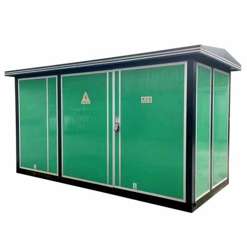
1. Why Does a Box-type Transformer Substation Face Short-Circuit Forces That a Building Substation Does Not?
A Box-type Transformer Substation is compact by design. The busbars are short and the clearances between phases are small. The electrodynamic force between two parallel conductors carrying a short-circuit current is proportional to the square of the current and inversely proportional to the distance between them. A smaller clearance therefore produces a larger force for the same current. The compact enclosure also limits the space available for bracing, so the busbar supports must be designed more carefully than in a spacious building substation. In our factory, we design the busbar supports and the connection hardware for the calculated short-circuit force at the rated withstand current. Lugao Power Co.,Ltd. has been manufacturing Box-type Transformer Substation units for over 15 years.
The location of the substation also matters. A box-type substation is often installed close to the load center, where the available fault current is high. A building substation may be fed through a longer cable, which reduces the fault current. The box-type unit must therefore be rated for a higher short-circuit level than its building counterpart, even when the transformer capacity is the same.
2. What Actually Happens Inside the Enclosure During a Short-Circuit Withstand Test?
The short-circuit withstand test applies the rated short-circuit current to the substation for the specified duration, usually 1 second or 3 seconds. During the test, three physical effects occur at the same time. The first is the electrodynamic force on the busbars and the winding. The force alternates at twice the power frequency and reaches a peak in the first half cycle. The second is the thermal effect. The current heats the conductors, and the temperature rise must stay below the limit of the insulation and the connection hardware. The third is the mechanical vibration. The enclosure and the supports must absorb the vibration without loosening. The table below shows the key test parameters and the acceptance criteria.
| Test parameter | Typical value | Acceptance criterion |
| Rated short-circuit current | 20 kA / 25 kA / 31.5 kA | Current maintained within tolerance |
| Duration | 1 s or 3 s | No interruption before the set time |
| Peak current factor | 2.5 times the RMS value | Peak current reached without flashover |
| Conductor temperature rise | Below insulation limit | No discoloration or deformation |
| Post-test dielectric | Applied after the test | No breakdown |
In our factory, the test is performed in an accredited high-power laboratory. The substation is instrumented with current shunts, thermocouples, and accelerometers. The recorded data is compared with the design calculation. Lugao Power Co.,Ltd. provides the test report and the recorded waveforms with the type test certificate.
3. How Does the Test Reveal Weak Points That a Routine Dielectric Test Cannot Find?
A routine dielectric test applies a high voltage but a low current. It verifies the insulation strength but does not verify the mechanical strength or the thermal stability. The short-circuit withstand test applies a high current at a low voltage. It verifies the mechanical and thermal performance. The two tests are complementary. The table below compares the two tests and the defects they can reveal.
| Test | Verification target | Defects revealed |
| Routine dielectric test | Insulation strength | Insulation defects, clearances, contamination |
| Short-circuit withstand test | Mechanical and thermal strength | Loose busbar supports, winding deformation, melted connections |
| Temperature rise test | Thermal design at rated load | Insufficient cooling, hot spots |
| Impulse voltage test | Lightning impulse strength | Insulation coordination defects |
Power equipment engineer's note: The short-circuit withstand test is the only test that reproduces the actual fault condition. A substation that passes the dielectric test but has a weak busbar support can fail mechanically during a fault, and the failure may cause a fire or a prolonged outage. In our factory, we perform the short-circuit withstand test on a representative sample of each design and we inspect the sample after the test. The inspection includes the torque check of every bolted connection and the dimensional check of the busbar. Lugao Power Co.,Ltd. provides the post-test inspection report with the type test certificate.
4. Why Do Test Setup, Calibration, and Post-Test Inspection Determine Whether the Result Is Trustworthy?
The test result is only as trustworthy as the test setup. The test circuit must be designed so that the impedance matches the required short-circuit current. The current transformers and the recording instruments must be calibrated within the last 12 months. The test duration must be controlled by a calibrated timer. The post-test inspection must be performed by a qualified inspector and documented with photographs. In our factory, we maintain a calibration log for every instrument used in the test. The log is reviewed by the quality manager before the test report is issued. We also invite the customer's representative to witness the test when requested. Lugao Power Co.,Ltd. provides the witness report and the calibration certificates with the test report.
We recommend that the buyer review the test laboratory accreditation and the calibration certificates before accepting the test report. A report from an unaccredited laboratory with expired calibration is not a reliable basis for confidence.
5. How Should Buyers Specify and Verify Short-Circuit Withstand Capability for a Box-type Substation?
The specification should include five items. The first is the rated short-circuit withstand current. The second is the duration. The third is the peak current factor. The fourth is the test standard, typically IEC 62271-202 or IEEE C37.20. The fifth is the documentation requirement, including the type test report, the post-test inspection report, and the calibration certificates. The verification should include a review of the type test report, a check of the rated current against the system fault level, and a third-party witness of the factory test if the unit is critical. In our factory, we provide the complete test documentation package with each order. Lugao Power Co.,Ltd. also offers a system fault level study to help the buyer select the correct withstand rating.
We recommend that the buyer specify a withstand current at least 10 percent above the calculated system fault level. This margin covers the growth of the fault level as the network expands and the tolerance of the protection settings.
Frequently Asked Questions About Short-Circuit Withstand Testing for Box-type Substations
Summary for Power Equipment Buyers and Engineers
Short-circuit withstand testing builds confidence in a Box-type Transformer Substation because it reproduces the actual fault condition and verifies the mechanical and thermal strength that a routine dielectric test cannot verify. The test applies the rated current for the specified duration and checks the busbar supports, the winding, and the connections after the test. The credibility of the test depends on the laboratory accreditation, the instrument calibration, and the post-test inspection. The specification should include the rated withstand current, the duration, the peak factor, the test standard, and the documentation. The verification should include a review of the type test report and a check of the rated current against the system fault level. Lugao Power Co.,Ltd. has been manufacturing Box-type Transformer Substation units for over 15 years and provides full short-circuit test documentation and system study support for our customers.