

How to Tell Whether a Circuit Needs a Fast-Acting or Time-Delay Fuse?
2026-10-23
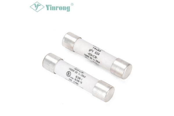
A maintenance technician replaces a blown fuse on a pump control panel. The replacement is the same rating as the original. The pump starts, runs for two seconds, and the fuse blows again. The technician replaces it a third time. The same result. The technician suspects a short circuit and begins tracing wiring. The actual problem is simpler: the original fuse was a time-delay type, and the replacement from the store room was a fast-acting type. The rating printed on the barrel was identical. The behavior under startup current was not. This is not an isolated case. The same confusion appears in solar combiner boxes, where a Solar Power Protection PV Fuse must ride through inverter startup surges while still clearing a DC arc fault. The choice between fast-acting and time-delay is not a matter of preference. It is a matter of reading the load.
1. Why Does the Same Fuse Fail Repeatedly in One Circuit but Last for Years in Another?
The answer is not in the fuse. It is in the current the circuit draws during its first few seconds of operation. A resistive heater draws a steady current from the moment the switch closes. A motor draws six to eight times its running current while the rotor accelerates. A transformer draws a short, sharp magnetizing current when it is energized. A power supply with a large capacitor bank draws a charging surge that can reach ten times its steady-state current. These are all normal operating conditions, not faults. A fuse that cannot distinguish a normal startup surge from a fault will open during startup. A fuse that delays too long will not open during a fault. The table below shows the startup behavior of common load types.
| Load type | Startup current vs. running current | Surge duration | What the fuse must do |
| Resistive heater | 1.0 – 1.2x | Less than 100 ms | Open quickly on any overcurrent |
| Induction motor | 6 – 8x | 200 – 800 ms | Ride through startup, open on sustained overload |
| Transformer energizing | 8 – 12x | 10 – 100 ms | Ride through inrush, open on fault |
| Capacitor charging | 5 – 15x | 5 – 50 ms | Ride through charging surge |
| Semiconductor control board | 1.0 – 1.5x | Negligible | Open within milliseconds of a fault |
In our factory, we test every Solar Power Protection PV Fuse against a simulated DC load profile that includes inverter startup surge and reverse current fault. The test confirms that the fuse rides through the surge without opening and clears the fault within the specified time. Zhejiang Galaxy Fuse Co., Ltd. has been manufacturing fuses for over 12 years.
2. What Happens Inside a Fuse When Current Rises Above Its Rating?
Every fuse works by the same principle: current passes through a metallic element, the element heats up, and when the temperature reaches the melting point of the element, the metal vaporizes and the circuit opens. The difference between a fast-acting fuse and a time-delay fuse is how much thermal mass the element has and how quickly it reaches that melting point. A fast-acting fuse uses a thin, low-mass element. The heat generated by an overcurrent raises the element temperature almost instantly. A time-delay fuse uses a larger element with more thermal mass, often with an alloying pellet that changes the melting behavior. The heat from a short surge is absorbed without reaching the melting point. Only a sustained overload accumulates enough heat to melt the element. The table below compares the thermal behavior of the two constructions.
| Characteristic | Fast-acting construction | Time-delay construction |
| Element thermal mass | Low | High |
| Time to reach melting point at 2x rated current | Less than 1 second | 5 – 30 seconds |
| Response to a 10 ms surge | Partial heating, may open | Negligible heating, does not open |
| Response to a sustained 2x overload | Opens quickly | Opens after the delay period |
| Typical marking | F, FF | T, TT |
Field note: The thermal difference explains why a time-delay fuse can carry a startup surge that is several times its rating without opening, while a fast-acting fuse of the same rating opens in milliseconds. The time-delay element is not slower because it is less sensitive. It is slower because it has more thermal mass to heat before it melts. In our factory, we measure the time-current curve of every production batch and compare it to the IEC 60269 gate limits. A fuse that falls outside the gate is rejected before shipment.
3. Which Load Characteristics Decide the Fuse Behavior?
The decision between fast-acting and time-delay is made by answering three questions about the load. What is the ratio of startup current to running current? How long does the startup surge last? And how sensitive is the load to a sustained overcurrent? A load with a high startup ratio and a long surge requires a time-delay fuse. A load with a low startup ratio and high sensitivity to overcurrent requires a fast-acting fuse. The table below maps common applications to the required behavior.
| Application | Startup ratio | Surge duration | Required behavior |
| Semiconductor control board | 1.0 – 1.5x | Negligible | Fast-acting (FF for very sensitive) |
| Resistive heating element | 1.0 – 1.2x | Less than 100 ms | Fast-acting |
| PV string combiner | 1.1 – 1.3x (reverse current fault can be 2x) | Fault is sustained | Fast-acting, DC-rated |
| Motor branch circuit | 6 – 8x | 200 – 800 ms | Time-delay |
| Transformer primary | 8 – 12x | 10 – 100 ms | Time-delay |
| Power supply with capacitor input | 5 – 15x | 5 – 50 ms | Time-delay |
A solar combiner is a useful example. The normal operating current of a PV string is essentially constant. There is no startup surge because the panels produce current as soon as irradiance is present. However, a reverse current fault, such as a shorted string or a ground fault, produces a sustained overcurrent that the fuse must clear quickly. For this reason, a Solar Power Protection PV Fuse is designed as a fast-acting DC-rated device, not a time-delay device. Zhejiang Galaxy Fuse Co., Ltd. manufactures PV fuses with a DC breaking capacity of 10 kA at 1000 V and a time-current curve that clears a 2x fault within 4 seconds.
4. How Do You Read a Time-Current Curve Before Choosing a Fuse?
The rated current printed on a fuse is a single point on a curve. The curve defines how long the fuse takes to open at every current level above the rating. Reading the curve is the only way to know whether the fuse will ride through a specific startup surge or open during it. The horizontal axis shows current as a multiple of the rating. The vertical axis shows opening time in seconds. To use the curve, plot the load's startup current and duration. If the point falls below the curve, the fuse will not open during startup. If the point falls above the curve, the fuse will open. For fault protection, plot the minimum fault current. If the point falls above the curve, the fuse will open within the required time. The table below shows how to plot three common load profiles against a time-current curve.
| Load profile | Plot point (current multiple, duration) | Curve position for correct selection |
| Motor startup (6x, 500 ms) | 6x rating, 0.5 seconds | Point must be below the curve |
| Transformer inrush (10x, 50 ms) | 10x rating, 0.05 seconds | Point must be below the curve |
| PV reverse current fault (1.5x, sustained) | 1.5x rating, greater than 10 seconds | Point must be above the curve |
Selection note: Two fuses with the same T or F marking can have different curves because the marking indicates a class, not a specific curve. Always request the time-current curve for the exact part number. In our factory, we provide the curve for each Solar Power Protection PV Fuse model in the datasheet. We also provide a curve-reading worksheet that the system designer can use to check the startup surge and the fault clearance time before the fuse is specified.
5. What Are the Two Most Common Mismatches and Their Consequences?
The first mismatch is a fast-acting fuse in a circuit with a high startup surge. The field symptom is a fuse that opens every time the equipment starts. The maintenance team often interprets this as a short circuit or a failing motor. They replace the fuse, test the wiring, and find nothing wrong. The fuse opens again on the next start. The real consequence is unnecessary downtime and unnecessary replacement of healthy components. The second mismatch is a time-delay fuse in a circuit with a sensitive load and a low startup surge. The field symptom is a semiconductor or control board that fails before the fuse opens. The fuse is still intact when the damaged board is removed. The maintenance team concludes that the fuse is working because it did not blow. The real consequence is that the protection did not operate in time to save the component. In our factory, we have analyzed returned fuses from both scenarios. The fast-acting fuse from the motor circuit shows a clean melt with no signs of a fault current. The time-delay fuse from the control board circuit shows no melting at all. Zhejiang Galaxy Fuse Co., Ltd. provides a failure analysis service that distinguishes between a fuse that opened correctly and a fuse that was mismatched to the load.
Frequently Asked Questions About Fuse Selection
Summary for Circuit Designers and Maintenance Teams
The choice between a fast-acting fuse and a time-delay fuse is determined by the load's startup current profile and the sensitivity of the downstream equipment to a sustained overcurrent. A fast-acting fuse protects semiconductor circuits, resistive loads, and PV combiners where the current is steady and the fault must be cleared quickly. A time-delay fuse protects motors, transformers, and capacitor-input power supplies where a normal startup surge would open a fast-acting fuse. The rated current alone is not enough to make the decision. The time-current curve must be checked against the startup surge and the minimum fault current. A mismatch produces either repeated nuisance blowing or delayed fault clearance. Zhejiang Galaxy Fuse Co., Ltd. has been manufacturing fuses for over 12 years and provides time-current curves, DC-rated PV fuses, and failure analysis support for our customers.
Zhejiang Galaxy Fuse Co., Ltd. manufactures fast-acting and time-delay fuses, including the Solar Power Protection PV Fuse series with 1000 V DC rating and 10 kA breaking capacity. We provide time-current curves, selection worksheets, and failure analysis for all of our products.