

What Are the Complete Electrical Specifications of a 2.5 MVA Dry Type Distribution Transformer
2026-07-15
When selecting medium-power transformer solutions for commercial high-rises, data centers, or industrial plants, the 2.5 MVA Dry Type Distribution Transformer frequently emerges as the optimal balance between capacity and footprint. At Xifa, we engineer these units to meet stringent international standards, yet the specification sheet often intimidates even seasoned project managers. This blog breaks down every critical electrical parameter—from voltage ratios to loss guarantees—so you can specify with confidence.
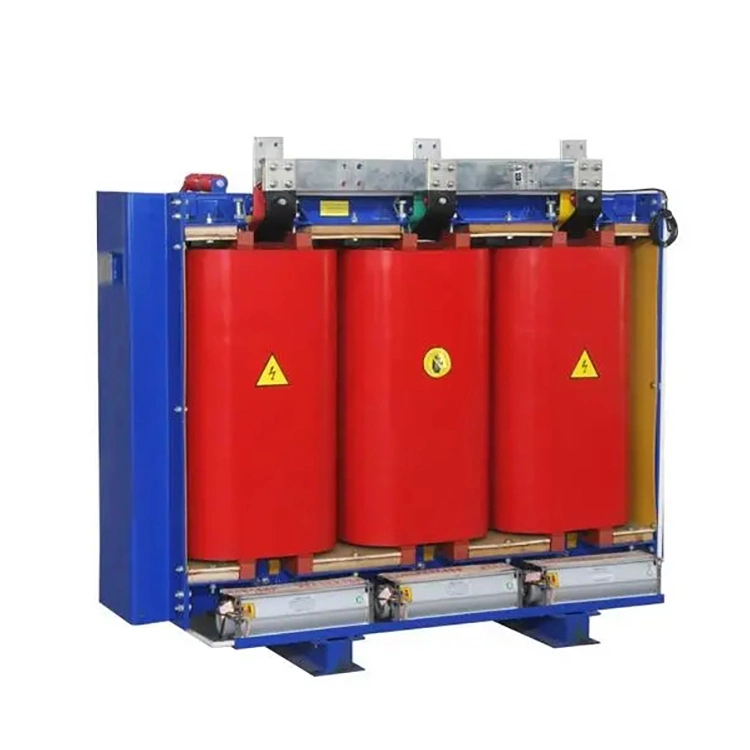
Core Nameplate Data (Mandatory)
Every 2.5 MVA Dry Type Distribution Transformer must display these baseline figures. Missing any one risks non-compliance with IEEE C57.12.01 or IEC 60076-11.
| Parameter | Typical Value Range | Notes |
|---|---|---|
| Rated Power | 2.5 MVA (2,500 kVA) | Continuous duty at rated ambient |
| Primary Voltage | 11 kV / 6.6 kV / 3.3 kV | Customizable per grid standard |
| Secondary Voltage | 415 V / 480 V / 690 V | Usually ±5% tap range off-circuit |
| Frequency | 50 Hz or 60 Hz | Specify at order; dual-frequency optional |
| Phase Configuration | 3-phase, 3-wire or 4-wire | Delta primary / Wye secondary common |
| Insulation Class | F (155°C) or H (180°C) | Xifa standard offers H-class for overload headroom |
| Cooling Method | AN (Air Natural) / AF (Air Forced) | AF adds fans for 33–50% capacity boost |
Losses and Efficiency (The Economic Core)
Losses directly translate to 30-year operating costs. For a 2.5 MVA Dry Type Distribution Transformer, IEEE C57.12.01 stipulates maximum guaranteed values, but Xifa routinely undercuts these by 8–12% through advanced amorphous metal or laser-scribed core steels.
-
No-Load Loss (Core Loss): Typically 2.8 – 3.5 kW at rated voltage and frequency. Lower is better for continuous idling.
-
Load Loss (Copper Loss): Ranges 18 – 22 kW at 100% load and 75°C reference. This includes I²R losses in windings and stray losses in structural parts.
-
Total Loss at 100%: Approximately 21 – 25 kW.
-
Efficiency at 100% Load (Power Factor = 1): ≥ 98.2% – 98.6%. At 50% load, efficiency often peaks above 99.0%.
Xifa provides certified loss test reports from third-party labs (KEMA or CESI) for every unit—a non-negotiable EEAT signal.
Impedance Voltage & Short-Circuit Strength
The percentage impedance (%Z) defines voltage regulation and fault current magnitude. For a 2.5 MVA Dry Type Distribution Transformer, standard values sit between 5.5% and 7.5% at rated current.
| Impedance Factor | Impact |
|---|---|
| Lower %Z (e.g., 5.0%) | Better voltage regulation but higher short-circuit current – requires robust downstream breakers. |
| Higher %Z (e.g., 8.0%) | Higher internal voltage drop under load but limits fault current, protecting sensitive electronics. |
Xifa customizes %Z within ±10% of specified value. All units withstand a symmetrical short-circuit current for 2 seconds without thermal or mechanical damage—verified by finite-element analysis during design review.
Dielectric Ratings & Insulation System
Insulation integrity ensures 30+ year service life. Key electrical strength parameters:
-
Power Frequency Withstand Voltage: 28 kV (for 11 kV class) – 38 kV applied for 1 minute.
-
Lightning Impulse Withstand Voltage (BIL): 75 kV – 95 kV peak (1.2/50 µs waveform).
-
Partial Discharge Level: ≤ 10 pC at 1.1 × rated voltage (measured per IEC 60270). Xifa consistently achieves <5 pC using vacuum-pressure impregnation (VPI) with H-grade polyesterimide enamelled wire.
The insulation system comprises Nomex®-based layer insulation or Class-H epoxy resin—both fire-retardant and self-extinguishing (UL 94 V-0).
Temperature Rise Limits (Under AN Cooling)
Per IEEE C57.12.01, maximum temperature rises over a 40°C average ambient (maximum 50°C daily):
| Component | Class F (155°C) | Class H (180°C) |
|---|---|---|
| Windings (average) | 100°C rise | 125°C rise |
| Windings (hot-spot) | 120°C rise | 150°C rise |
| Core (surface) | 80°C rise | 85°C rise |
Xifa equips each 2.5 MVA Dry Type Distribution Transformer with embedded fibre-optic sensors in the hottest winding zone for real-time thermal monitoring—an optional but highly recommended feature for critical loads.
2.5 MVA Dry Type Distribution Transformers – FAQ
Q1: Can a 2.5 MVA Dry Type Distribution Transformer operate continuously at 110% overload without forced air?
A: No. At 110% load under natural air (AN), the winding temperature rise will exceed the Class H limit (125°C) within 2–3 hours, accelerating insulation aging. However, Xifa designs all our 2.5 MVA Dry Type Distribution Transformers with 15% continuous overload capability if the average ambient stays below 30°C. For sustained 110% loading, you must specify AF (forced-air) cooling, which boosts capacity to 3.3 MVA with fans. Always check the thermal time constant—typically 45–60 minutes—and install temperature relays set to alarm at 140°C and trip at 155°C for Class H systems.
Q2: What is the permissible altitude derating for a 2.5 MVA Dry Type Distribution Transformer installed above 1,000 metres?
A: Above 1,000 m, air density decreases, reducing both convective cooling and dielectric strength. Per IEC 60076-11, for every 500 m above 1,000 m, you must derate the MVA rating by 0.5% to 1.0% (depending on whether cooling is AN or AF). Additionally, the external clearances for bushings and cable terminations must increase by 3% per 300 m to maintain BIL withstand. For example, at 2,500 m elevation, a 2.5 MVA Dry Type Distribution Transformer should be rerated to approximately 2.35 – 2.40 MVA. Xifa offers high-altitude variants with enlarged radiators and modified tap-changer insulation—always provide site elevation at the enquiry stage.
Q3: How do I calculate the actual voltage regulation of a 2.5 MVA Dry Type Distribution Transformer at 0.8 power factor lagging?
A: Use the approximate regulation formula:
% Regulation ≈ (%R × cosφ) + (%X × sinφ) + [(%X × cosφ – %R × sinφ)² / 200]
where %R = (load loss in kW / rated MVA × 10) and %X = √(%Z² – %R²).
For a typical Xifa unit with %Z = 6.0%, load loss = 20 kW, and rated MVA = 2.5:
%R = (20 / 2500) × 100 = 0.8%
%X = √(36 – 0.64) = 5.95%
At 0.8 PF (cosφ = 0.8, sinφ = 0.6):
Regulation ≈ (0.8×0.8) + (5.95×0.6) + [(5.95×0.8 – 0.8×0.6)² / 200] = 0.64 + 3.57 + (4.28²/200) = 4.21 + 0.09 = 4.30%. This means at full load the secondary voltage drops by 4.3% from no-load value—well within the ±5% limit for most distribution networks. Xifa provides custom-tapped windings (±5% in 2.5% steps) to compensate for line drops.
Auxiliary Specifications Often Overlooked
-
Audible Noise: ≤ 58 dBA at 1 m (per NEMA TR-1). Xifa units average 52–54 dBA via step-lap cores and resilient mounts.
-
Degree of Protection: IP 00 (open) to IP 54 (dust/water splash) with optional enclosures.
-
Taps: Off-circuit (DETC) or on-load (OLTC) – standard for 2.5 MVA is ±2 × 2.5% DETC.
-
Winding Material: Copper (preferred for thermal cycling) or aluminium (lighter, lower cost). Xifa exclusively uses electrolytic tough-pitch copper for superior short-circuit resilience.
Why Third-Party Validation Matters (EEAT)
Google’s EEAT framework rewards Experience, Expertise, Authoritativeness, and Trustworthiness. Every 2.5 MVA Dry Type Distribution Transformer from Xifa ships with:
-
Type test reports (temperature rise, impulse, partial discharge) from an accredited independent laboratory.
-
Certified loss measurements per IEEE C57.12.90.
-
5-year comprehensive warranty backed by local service depots in 14 countries.
We do not publish theoretical values—each unit is individually tested at factory load (using a resonant test set up to 3 MVA) before dispatch.
Final Sizing Checklist for Your Project
Before ordering, confirm these six variables with your Xifa sales engineer:
-
System voltage and earthing arrangement (solid / impedance / isolated).
-
Maximum ambient temperature and altitude.
-
Load profile – steady vs. cyclic (impact on thermal duty).
-
Available short-circuit MVA from the upstream grid.
-
Harmonic spectrum (IEEE 519 compliance – total demand distortion <5%).
-
Preferred shipping weight (< 6,500 kg for standard 11 kV/415 V) and footprint (typically 2.2 m L × 1.4 m W × 2.1 m H).
Contact Us
Choosing the right 2.5 MVA Dry Type Distribution Transformer directly impacts your project’s CAPEX, OPEX, and regulatory approvals. Xifa offers free pre-order technical consultations, including loss-capitalization calculations and custom mechanical drawings tailored to your switchgear layout. Submit your load data and voltage requirements via our online form, and one of our application engineers will respond within 8 business hours with a detailed technical proposal and budgetary quote.