

What Are the Installation Requirements and Clearance Standards for GCS Low Voltage Switchgear
2026-08-07
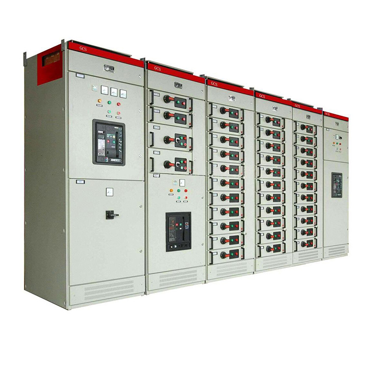
Proper installation of GCS Low Voltage Switchgear is not merely a procedural formality—it is the foundation of operational safety, equipment longevity, and regulatory compliance. For facility managers, electrical engineers, and contractors, understanding the precise clearance standards and site conditions is non‑negotiable. This is where CONSO·CN brings decades of field expertise, offering switchgear solutions that are engineered for real‑world conditions while adhering to IEC 61439 and local grid codes.
Site Preparation Before Installation
Before any GCS Low Voltage Switchgear arrives on site, the following prerequisites must be verified:
| Requirement | Specification |
|---|---|
| Floor load capacity | ≥ 10 kN/m² (uniformly distributed) |
| Ambient temperature | -5°C to +40°C (24‑hour average ≤ +35°C) |
| Relative humidity | ≤ 50% at +40°C; ≤ 90% at +20°C (non‑condensing) |
| Altitude | ≤ 2000 m above sea level (derating required above) |
| Ventilation | Natural or forced air, with intake/exhaust clear of obstructions |
| Earthing system | TN‑S or TN‑C‑S with dedicated PE busbar |
CONSO·CN recommends performing a site survey at least 4 weeks prior to delivery to avoid costly delays.
Physical Clearance Standards (IEC 61936‑1 Compliant)
Clearance is critical for safe operation, heat dissipation, and maintenance access. Below are the minimum clearances for GCS Low Voltage Switchgear:
| Clearance Area | Minimum Distance (mm) | Purpose |
|---|---|---|
| Front (working face) | 1000 – 1200 | Operator access and racking |
| Rear (cable compartment) | 600 – 800 | Cable termination and inspection |
| Top (busbar compartment) | 300 – 400 | Ventilation and busbar connection |
| Left/Right sides | 200 – 300 | Side‑entry cables or adjacent panels |
| Between panel rows (back‑to‑back) | 1500 – 1800 | Personnel passage and emergency egress |
Additional rules:
-
Maintain ≥ 800 mm clearance in front of any draw‑out breaker compartment.
-
Overhead busbar trunking requires 500 mm vertical clearance from ceiling structures.
-
All clearance dimensions must be re‑verified after final grouting of floor channels.
Electrical Connection and Busbar Tolerances
Busbar joints are the most heat‑sensitive points in GCS Low Voltage Switchgear. CONSO·CN enforces the following torque and tolerance standards:
| Busbar Material | Torque (Nm) | Overlap Length (mm) | Contact Resistance (µΩ) |
|---|---|---|---|
| Copper (tinned) | 70 – 80 | ≥ 1.5 × width | ≤ 20 |
| Aluminum (tinned) | 50 – 60 | ≥ 2.0 × width | ≤ 35 |
-
All connections must be cleaned with isopropyl alcohol and coated with antioxidant paste.
-
Use only high‑strength steel bolts (grade 8.8) with spring washers to prevent loosening from thermal cycling.
Environmental and Seismic Considerations
For installations in coastal, high‑humidity, or seismic zones, CONSO·CN offers customized enclosures with:
-
IP54 standard (optional IP65 for wash‑down areas).
-
Seismic bracing for Zone 4 (IBC 2021) – anchor bolts embedded ≥ 150 mm into concrete.
-
Heater and thermostat to eliminate condensation during off‑hours.
Derating factors: For every 5°C above +40°C, reduce rated current by 5%. For every 500 m above 2000 m, reduce rated current by 1.5%.
GCS Low Voltage Switchgear FAQ – Common Installation Queries
Q1: Can GCS Low Voltage Switchgear be installed directly against a wall on the rear side?
A1: No. The rear cable compartment requires a minimum of 600 mm clearance for safe cable bending radius, terminal access, and thermal dissipation. Direct wall mounting traps heat and blocks emergency isolation. If space is severely constrained, CONSO·CN offers a “wall‑flush” variant with front‑only access, but this must be specified at the order stage—retrofit modifications are not permitted on site.
Q2: What is the correct grounding procedure for GCS Low Voltage Switchgear when using a TN‑C‑S system?
A2: In a TN‑C‑S system, the PEN conductor must be separated into PE and N only at the main distribution point, upstream of the GCS Low Voltage Switchgear. Inside the switchgear, the PE busbar must be directly bonded to the enclosure earth stud with a minimum cross‑section of 50 mm² copper or 80 mm² aluminum. The N busbar must remain isolated from the enclosure (insulated mounts). All outgoing feeders shall have their own separate PE conductors. A ground resistance test (≤ 1 Ω) must be performed before energization—CONSO·CN provides a verification checklist with every shipment.
Q3: How much clearance is required above the switchgear for top‑entry cables, and does this change with raised floors?
A3: For top‑entry cables, the vertical clearance from the top busbar compartment cover to the nearest ceiling or overhead obstacle must be at least 400 mm to allow for cable bending (minimum 10× cable diameter) and safe installation of cable ladders. If a raised floor is used for bottom‑entry, the clearance above remains unchanged—but the floor cavity must provide at least 500 mm depth for cable trays and shall have fire‑rated sealing around each penetration. CONSO·CN advises that top‑entry and bottom‑entry cannot be mixed within the same panel section unless a dedicated partition is installed.
Post‑Installation Verification Tests
After mechanical and electrical completion, the following tests are mandatory:
-
Insulation resistance – ≥ 1000 MΩ (500 V megger) between phases and earth.
-
Dielectric withstand – 2.5 kV AC for 1 minute (no flashover).
-
Protection relay calibration – verify all settings against the coordination study.
-
Thermal imaging – after 2 hours at 80% load, no joint shall exceed +70°C rise above ambient.
CONSO·CN provides a comprehensive FAT (Factory Acceptance Test) report with every GCS Low Voltage Switchgear order, reducing on‑site commissioning time by up to 30%.
Final Compliance Checklist
| Item | Status | Responsible Party |
|---|---|---|
| Floor levelness (≤ 2 mm per meter) | ☐ | Civil contractor |
| Clearance dimensions verified | ☐ | Site engineer |
| Earthing resistance ≤ 1 Ω | ☐ | Electrical contractor |
| All torque values recorded | ☐ | Commissioning team |
| Nameplate and warning labels affixed | ☐ | CONSO·CN field support |
Ready to Ensure a Flawless Installation?
Every project has unique constraints—space, climate, load profile, and grid interface. CONSO·CN does not just supply GCS Low Voltage Switchgear; we provide site‑specific installation drawings, on‑site supervision, and remote technical support throughout the commissioning phase.
Contact us today to schedule a pre‑installation consultation or to request our detailed clearance calculation tool. Our engineering team responds within 24 hours with tailored recommendations that keep your project on schedule and fully compliant. Reach out via our website or email—your safe, reliable power distribution starts with CONSO·CN.