

What Changes When HV Switchgear Moves Into Box-type Transformer Substation Tank?
2026-11-02
A design engineer is asked to convert a conventional indoor distribution room into a compact Box-type Transformer Substation. The indoor room had a 2.2 meter aisle in front of the switchgear, a separate ventilation system, and a dedicated earthing grid. The compact substation has 1.2 meters of clearance, a shared enclosure with the transformer, and a single earthing terminal. The engineer must review every assumption in the original design. The switchgear itself does not change. What changes is the environment around it, and that environment determines the insulation distances, the temperature rise, the arc fault pressure relief, and the maintenance access. This guide explains what changes when HV switchgear moves into the substation tank.
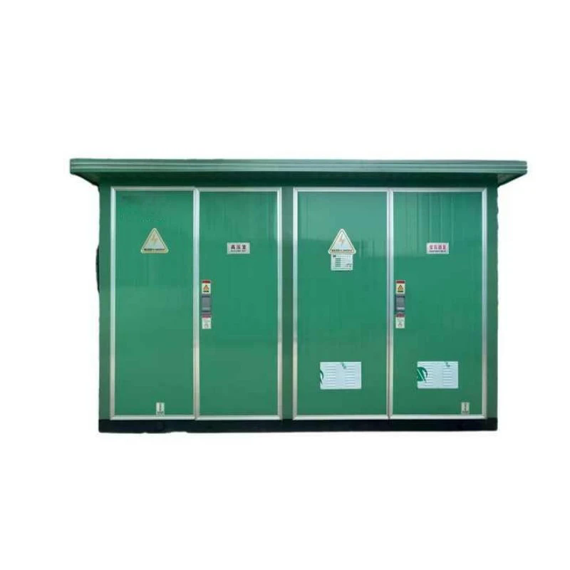
1. Why Does Moving HV Switchgear Indoors Change Every Design Assumption?
The indoor distribution room and the compact substation are different design environments. The indoor room has generous space, independent ventilation, and a clear separation between the switchgear and the transformer. The compact substation shares the enclosure between the switchgear, the transformer, and the low voltage panel. The space is limited, the heat sources are close together, and the maintenance access is through a single door. The engineer cannot simply transfer the indoor layout into the compact enclosure. The layout must be re-engineered for the smaller volume. In our factory, we manufacture Box-type Transformer Substation units with integrated HV switchgear. Lugao Power Co.,Ltd. has been manufacturing compact substations for over 15 years.
The design assumptions that change include the clearances between live parts and earthed parts, the ventilation air path, the earthing conductor arrangement, the interlocking logic, and the arc fault pressure relief direction. Each of these is discussed in the following sections.
2. How Does the Enclosure Geometry Constrain Switchgear Layout and Arc Clearance?
The compact enclosure limits the distance between the switchgear and the walls, the distance between adjacent switchgear panels, and the distance between the switchgear and the transformer. The phase-to-phase and phase-to-earth clearances must still meet the insulation requirement for the rated voltage. The clearances are defined by the applicable standard, such as IEC 62271-200 for metal enclosed switchgear. The enclosure geometry must accommodate these clearances plus the operating space for the operator and the maintenance access. The table below compares the indoor room and the compact substation for the key dimensional parameters.
| Parameter | Indoor distribution room | Box-type Transformer Substation |
| Front aisle width | 2.0 – 2.5 m | 1.0 – 1.5 m |
| Side clearance to wall | 0.8 – 1.0 m | 0.3 – 0.5 m |
| Phase-to-earth clearance (12 kV) | 125 mm | 125 mm (must be maintained) |
| Pressure relief direction | Upward through ceiling | Upward and outward through louver |
| Maintenance access | Front and rear doors | Front door only (rear is sealed) |
The table shows that the phase-to-earth clearance does not change, but the space around the switchgear is reduced. The reduced space means that the maintenance access is limited to the front of the switchgear, and the rear of the switchgear must be sealed or the switchgear must be a front-access design. In our factory, we use front-access switchgear for compact substations so that the maintenance can be performed without removing the switchgear from the enclosure. Lugao Power Co.,Ltd. provides the dimensional drawing of the switchgear and the enclosure for the design review.
3. What Happens to Heat Dissipation When Switchgear and Transformer Share One Tank?
The transformer generates heat from the core losses and the winding losses. The switchgear generates heat from the conductor resistance and the contact resistance. When both are in the same enclosure, the heat loads add together, and the ventilation must remove the total heat. If the ventilation is inadequate, the temperature inside the enclosure rises, and the switchgear and the transformer must be derated. The table below shows the ventilation requirement and the derating factor for different capacity combinations.
| Transformer capacity | Switchgear rating | Total heat load | Ventilation method | Derating factor |
| 630 kVA | 630 A | 8.5 kW | Natural ventilation | 1.0 (no derating) |
| 1,000 kVA | 630 A | 12.0 kW | Natural ventilation with louver | 1.0 |
| 1,250 kVA | 1,250 A | 15.5 kW | Forced ventilation (fans) | 0.95 |
| 1,600 kVA | 1,250 A | 19.0 kW | Forced ventilation (fans + thermostat) | 0.90 |
| 2,000 kVA | 2,000 A | 24.0 kW | Forced ventilation + heat shield | 0.85 |
Design engineer's note: The derating factor applies to both the transformer and the switchgear. A 1,600 kVA transformer with a 1,250 A switchgear in a forced ventilation enclosure may need to be operated at 90 percent of its rating. The design engineer must calculate the total heat load and select the ventilation method accordingly. In our factory, we use a thermal simulation to predict the temperature distribution inside the enclosure before the design is finalized. Lugao Power Co.,Ltd. provides the thermal simulation report with the design package.
4. Why Do Earthing, Interlocking, and Maintenance Access Become More Critical in a Shared Enclosure?
In a shared enclosure, the earthing system must connect the switchgear frame, the transformer tank, and the enclosure body to a single earthing terminal. The earthing conductor must be sized for the maximum fault current and must be continuous. The interlocking system must prevent the operator from opening the switchgear door while the switch is closed, and from closing the switch while the door is open. The interlocking must also coordinate with the transformer, so that the transformer cannot be energized while the switchgear is in a maintenance state. In our factory, we test the interlocking logic on every unit before shipment. We also measure the earthing resistance between the switchgear frame and the earthing terminal. The resistance must be below 0.1 ohm. Lugao Power Co.,Ltd. provides the interlocking test report and the earthing resistance measurement with the shipment.
The maintenance access is more critical because the space is limited. The operator must be able to rack out the circuit breaker, test the cables, and replace a fuse without removing the switchgear from the enclosure. We design the enclosure with a removable front panel and a cable access cover so that the maintenance can be performed from the front.
5. How Should Engineers Specify and Verify a Box-type Transformer Substation With Integrated HV Switchgear?
The specification should include six items. The first is the switchgear type, the rated voltage, the rated current, and the breaking capacity. The second is the enclosure protection rating. The third is the ventilation method and the derating factor. The fourth is the interlocking requirement. The fifth is the earthing requirement. The sixth is the maintenance access requirement. The verification should include five tests. The first is the dielectric test. The second is the temperature rise test. The third is the interlocking function test. The fourth is the earthing resistance test. The fifth is the internal arc test, if the standard requires it. In our factory, we perform these tests on every unit and provide the test report with the shipment. Lugao Power Co.,Ltd. also offers a design review with the customer's switchgear and transformer data.
We recommend that the engineer verify the enclosure dimensions against the switchgear dimensional drawing before the design is released. A switchgear that fits in the indoor room may not fit in the compact enclosure if the front aisle is reduced or if the cable access is blocked.
Frequently Asked Questions About HV Switchgear in Box-type Transformer Substation Tanks
Summary for Switchgear Design Engineers
Moving HV switchgear into a Box-type Transformer Substation changes the geometry, the heat dissipation, the earthing, the interlocking, and the maintenance access. The clearances must still meet the insulation requirement, but the space around the switchgear is reduced. The heat load of the transformer and the switchgear add together, and the ventilation must be sized for the total load. The earthing must connect all metallic parts to a single terminal. The interlocking must prevent unsafe access. The specification should include the switchgear rating, the enclosure rating, the ventilation method, the interlocking requirement, and the earthing requirement. The verification should include dielectric, temperature rise, interlocking, earthing, and internal arc tests. Lugao Power Co.,Ltd. has been manufacturing compact substations for over 15 years and provides full design and verification support for integrated switchgear projects.