

Where Are Low Voltage Circuit Breakers Used in Industrial DC Systems?
2026-11-20
A battery energy storage site experienced a short circuit on a 750 V DC feeder. The protection device was a standard AC miniature circuit breaker. The breaker tripped, but the arc did not extinguish, and the fault current continued until the upstream fuse cleared the circuit. The investigation found that the breaker had no DC rating and no magnetic arc blowout. The device was never designed to interrupt a DC arc. A Low Voltage Circuit Breaker for DC service must be selected for the DC voltage, the DC current, the time constant, and the fault level. Our factory has reviewed many DC protection schemes, and the same mistake appears in different forms. This guide explains where DC low voltage breakers are used, and what must be checked before installation.
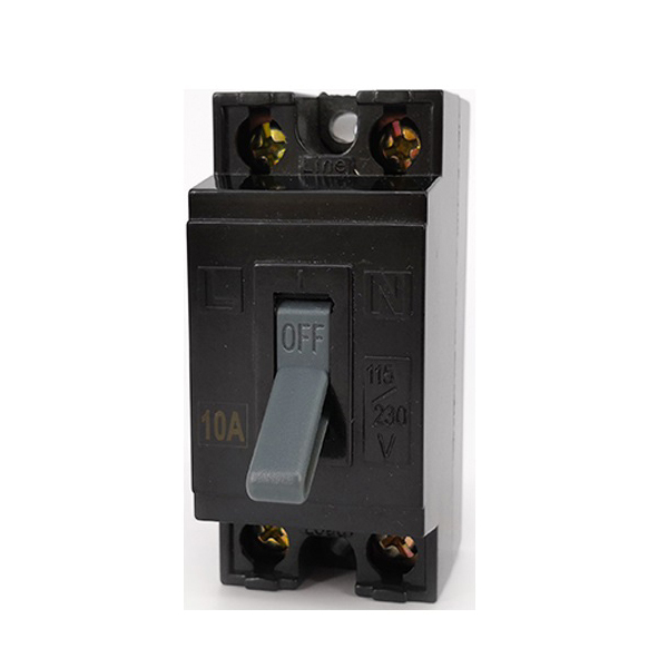
1. Why Does a DC Arc Behave Differently From an AC Arc in Industrial Systems?
An AC arc is extinguished at the current zero crossing, which occurs twice per cycle. The breaker can use the natural zero to interrupt the arc and recover dielectric strength. A DC arc has no natural zero crossing. The current continues to flow until the arc voltage exceeds the system voltage, and the arc energy must be dissipated by the breaker. The arc lasts longer, the contact erosion is greater, and the ionized gas remains conductive for a longer time. A DC breaker therefore needs a magnetic blowout coil, a longer arc chute, and a higher arc voltage capability. The polarity of the connection also matters, because the magnetic blowout force depends on the current direction. In our test lab, a 250 V DC arc at 100 A can sustain for tens of milliseconds longer than an AC arc of the same current. That difference is enough to destroy a breaker that is not DC rated.
The practical consequence is that an AC breaker may appear to work in a DC system at low voltage and low current, and then fail at the first real fault. The failure is not a nuisance trip. It is a failure to clear, which can cause fire, equipment damage, and injury. The buyer should treat the DC rating as a hard requirement, not as a margin.
2. Where Are Low Voltage Circuit Breakers Applied Across Industrial DC Installations?
Low voltage DC systems appear in several industrial sectors. The protection requirements differ by voltage, current, and fault level. The table below lists the common application points and the typical breaker configuration. These are engineering ranges, not fixed values, and the final selection depends on the system study.
| Application | Typical DC voltage | Typical current | Breaker configuration | Main selection issue |
| Photovoltaic DC side | 600 to 1500 V | 10 to 250 A | Two pole or three pole in series | Critical current and polarity |
| Battery storage cluster | 400 to 1000 V | 100 to 630 A | Two pole or three pole in series | High fault current and DC rating |
| DC charging station | 200 to 1000 V | 50 to 250 A | Two pole in series | Polarity and arc interruption |
| Electrolysis and plating | 24 to 200 V | 100 to 2000 A | Single pole or two pole | Low voltage and high current |
| Data center DC bus | 240 or 400 V | 16 to 100 A | Single pole or two pole | Selective coordination |
| DC microgrid | 48 to 375 V | 10 to 200 A | Single pole or two pole | Bidirectional fault current |
A Low Voltage Circuit Breaker used in these locations must be selected for the specific DC voltage and the specific fault level. The same frame size may have different DC ratings depending on the number of poles in series and the time constant of the circuit. Our factory keeps the DC test data for each frame size and shares it with the system designer. Wenzhou Zhechi Electric Co., Ltd has supplied DC breakers for photovoltaic and storage projects, and we review the application before quoting.
3. What Breaker Parameters Must Match a DC System Before Installation?
The first parameter is the rated DC voltage. A breaker that is rated for 250 V DC cannot be used on a 750 V DC feeder, even if the AC rating is 690 V. The second parameter is the rated DC current, which is affected by the ambient temperature and the mounting enclosure. The third parameter is the DC breaking capacity, which must exceed the prospective fault current at the installation point. The fourth parameter is the time constant of the circuit, because a longer time constant means a longer arc and a harder interruption. The fifth parameter is the trip curve, which must coordinate with the upstream and downstream devices. The table below compares the key parameters of an AC breaker and a DC breaker. Our engineers check these parameters against the system study before a breaker is released.
| Parameter | AC breaker | DC breaker |
| Arc extinction | Natural current zero | No current zero, magnetic blowout |
| Pole use | One pole often sufficient | Series poles to share arc voltage |
| Polarity | Not marked | Line and load polarity marked |
| Trip element | Thermal magnetic common | Hydraulic magnetic common |
| DC rating | Not stated | Explicit DC voltage and time constant |
| Critical current | Not applicable | May not trip below a critical current |
| Test evidence | AC test data | Manufacturer DC test data |
Application engineer's note: The time constant is the parameter that is most often omitted from the purchase order. A breaker that is tested with a 5 millisecond time constant may not clear a fault in a circuit with a 15 millisecond time constant. The arc energy is higher and the arc chute is stressed beyond its design. Our factory asks for the circuit inductance and the time constant before recommending a DC breaker. Wenzhou Zhechi Electric Co., Ltd includes the DC test condition in the datasheet so that the designer can compare it with the system condition.
4. Why Do Polarity, Series Connection, and Trip Curve Decide Whether the Breaker Clears a DC Fault?
The magnetic blowout coil in a DC breaker produces a force that pushes the arc into the arc chute. The force depends on the current direction. If the breaker is connected with the wrong polarity, the force pushes the arc toward the contact instead of the chute, and the arc does not extinguish. This is why DC breakers are marked with line and load terminals. The series connection is also critical. Each pole has a limited arc voltage capability. Two or three poles in series divide the arc voltage and allow the breaker to clear a higher DC voltage. The series connection must be made according to the manufacturer instruction, with the correct polarity for each pole. A simple jumper that does not respect the polarity can defeat the series arrangement. Our test data shows that a two pole series connection can clear a DC voltage that a single pole cannot, but only when the polarity is correct.
The trip curve is the third factor. A thermal magnetic breaker may not trip quickly at a low overload, and a DC fault current that is below the magnetic trip threshold can persist. A hydraulic magnetic breaker with a defined trip band is often preferred for DC because the magnetic force is independent of the ambient temperature. The designer should check the trip curve against the fault current and the coordination requirement. A breaker that clears the fault but also trips the upstream device is not selective, and the whole line is lost.
5. How Should Engineers Specify and Verify Low Voltage Circuit Breakers for DC Service?
The specification should include the DC voltage, the DC current, the time constant, the prospective fault current, the number of poles in series, the polarity marking, the trip curve, and the enclosure rating. The verification should include the DC test certificate, the polarity check, the series connection check, the insulation resistance test, and the trip test at the expected fault current. Our engineers review the system study and the breaker datasheet side by side before the order is released. Wenzhou Zhechi Electric Co., Ltd provides the DC test certificate and the connection diagram with each DC breaker order.
The buyer should also verify that the breaker is not a repurposed AC device. A breaker that carries an AC rating and a separate DC rating may be acceptable if the DC rating covers the application, but the DC test condition must be reviewed. A breaker that carries only an AC rating should not be used in a DC system, regardless of the voltage. The cost difference between an AC breaker and a DC breaker is small compared with the cost of a failure to clear a fault.
What Questions Come Up Most Often During DC Breaker Selection?
Summary and Recommendation: Low voltage circuit breakers are used in industrial DC systems wherever a DC feeder needs overload and short circuit protection. The common locations are photovoltaic DC side, battery storage clusters, DC charging stations, electrolysis and plating rectifiers, data center DC buses, and DC microgrids. The breaker must be selected for the DC voltage, the DC current, the time constant, the fault level, the number of series poles, and the polarity. An AC breaker is not a substitute. The buyer should request the DC test certificate, the polarity marking, the series connection diagram, and the trip curve before installation. When these items are verified, the breaker clears the DC fault and the system remains protected.