

Why Do Compact Substations Require Carefully Selected Isolator Switch Equipment?
2026-11-16
A maintenance crew arrives at a compact substation to replace a cable termination. The upstream breaker is opened, the lockout tag is applied, and the crew looks for the visible isolation point. The Isolator Switch is mounted behind the cable compartment, its handle is blocked by a fuse carrier, and the operating rod cannot be inserted without removing a panel. The crew spends an extra hour removing panels before the isolation can be confirmed. The switch itself is electrically adequate, but the selection was made for the electrical rating only and not for the mechanical and spatial conditions of the compact enclosure. This is why isolator switch selection in compact substations is a system decision, not a catalog lookup. Our factory supplies Isolator Switch units for compact substations and reviews the installation envelope with the switchgear designer before production. Wenzhou Xifa Electrical Equipment Co., Ltd. has been manufacturing isolator switches for over 12 years.
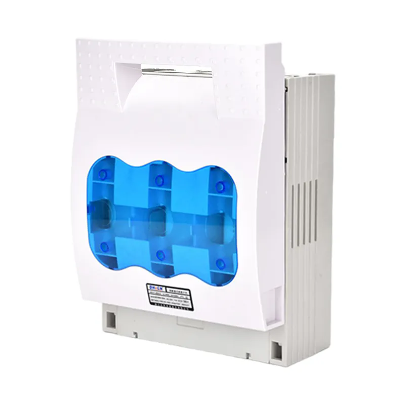
1. Why Does a Compact Substation Leave No Room for an Oversized Isolator Switch?
A compact substation is defined by its footprint. The enclosure is sized to the minimum that satisfies the electrical clearances, the cable bending radii, and the maintenance access. The Isolator Switch must fit within that envelope without intruding into the cable compartment or the operating aisle. The critical dimensions are the pole center distance, the arc chute depth, the operating shaft length, and the handle sweep. A switch that is one frame size larger may fit the busbar but may not allow the door to close or may block the fuse access. In our factory, we prepare a dimensional drawing for each switch and check it against the enclosure drawing before the order is released. Our engineering team has seen compact substations where a switch was selected by current rating alone and had to be replaced because the operating handle could not be reached with a gloved hand. The cost of the replacement was small compared with the cost of the enclosure modification.
The space constraint also affects the visible isolation point. The switch must be mounted so that the open contacts are visible through the inspection window or through the open door. If the switch is mounted too deep in the enclosure, the visible break cannot be confirmed from the operating position, and the maintenance crew must rely on the position indicator alone. The selection must consider the viewing angle, not just the electrical clearance.
2. What Happens to Safety and Visible Isolation When the Switch Is Not Rated for the Fault Level?
The Isolator Switch is not a fault-breaking device, but it must withstand the fault current that flows through it while the upstream breaker clears the fault. The switch must have a rated short-time withstand current and a rated peak withstand current that match the fault level at the installation point. If the switch is under-rated, the contacts may weld or the support insulators may crack during a fault, and the switch may not be able to open after the fault is cleared. The visible isolation is then lost, and the maintenance crew cannot confirm the safe condition. The table below compares the main isolator switch types used in compact substations and their suitability.
| Switch type | Typical fault withstand | Visible break | Compact enclosure suitability |
| Indoor load break switch with fuse | 20 kA / 1 s | Yes, through window | Good for ring main units |
| Draw-out isolation truck | 25 kA / 3 s | Yes, when withdrawn | Requires withdrawal space |
| Fixed isolator with earthing switch | 25 kA / 1 s | Yes, through door | Good for small enclosures |
| Fuse switch disconnector | 16 kA / 1 s | Yes, through window | Good for small transformer feeders |
Switchgear designer's note: The fault withstand rating must be checked against the prospective fault current at the switch location, not at the substation incoming terminals. The fault current drops along the cable, and a switch at the end of a long feeder may see a lower fault current than a switch at the busbar. Our factory provides the short-time and peak withstand test report for each switch type, and we recommend that the designer verify the rating against the calculated fault level at the actual mounting point. Wenzhou Xifa Electrical Equipment Co., Ltd. can review the fault calculation with the customer if the data is available.
3. How Do Environmental and Maintenance Conditions Change the Switch Selection?
A compact substation is often installed outdoors or in a semi-enclosed shelter. The switch is exposed to humidity, condensation, dust, and temperature cycling. The insulation material and the contact plating must be selected for the environment. A switch with a low creepage distance may flash over in a humid, polluted location. A switch with a thin contact plating may corrode and overheat. The maintenance condition also matters. A switch that is operated frequently needs a robust operating mechanism and a clear position indicator. A switch that is operated only for annual maintenance can be simpler, but it must still open reliably after long periods of inactivity. In our factory, we offer Isolator Switch units with different insulation materials and contact platings for different environments. Our test laboratory performs a humidity and a salt spray test on the switch assemblies. Wenzhou Xifa Electrical Equipment Co., Ltd. provides the test report with each switch and recommends the maintenance interval based on the operating frequency and the environment.
The environmental selection also affects the enclosure. A switch that is designed for indoor use may not be suitable for a compact substation that is installed in a coastal area. The enclosure must have the correct ingress protection, and the switch must be mounted so that condensation drains away from the insulators. The selection should consider the enclosure as part of the switch system, not as a separate item.
4. Why Does the Coordination Between Switch, Fuse, and Cable Termination Decide Reliability?
The Isolator Switch is one component in a chain that includes the fuse, the cable termination, and the earthing switch. The chain works only if the components are coordinated. The fuse must be selected so that it protects the cable and the transformer but does not operate on the normal inrush current. The switch must be rated for the fuse current and for the fault current that the fuse lets through. The cable termination must be spaced so that the cable bending radius is respected and the termination is accessible for testing. In our factory, we review the coordination for each compact substation order and we provide a single line diagram that shows the switch, the fuse, the cable, and the earthing point. Our production team also checks the cable termination space on the switch drawing before the enclosure is fabricated. Wenzhou Xifa Electrical Equipment Co., Ltd. has supplied switch and fuse packages for compact substations in several markets, and we have learned that the coordination review prevents most of the site modifications.
The earthing switch is often integrated with the isolator. The earthing switch must be rated for the fault current and must be interlocked with the main switch so that it cannot be closed while the main contacts are closed. The interlock must be mechanical, not only electrical, because the maintenance crew may operate the switch under local control. The switch selection should include the earthing switch and the interlock as part of the same assembly.
5. How Should Engineers Specify and Verify an Isolator Switch for a Compact Substation?
The specification should include the rated voltage, the rated current, the short-time withstand current, the peak withstand current, the number of poles, the operating mechanism, the mounting orientation, the enclosure protection, and the interlock requirement. The specification should also include the visible break requirement and the inspection access. The verification should include four checks. The first is the dimensional check against the enclosure drawing. The second is the fault withstand test report review. The third is the mechanical operation test, including the interlock test. The fourth is the insulation resistance test after installation. In our factory, we perform these checks on every switch and provide the test report with the shipment. Our quality team also photographs the switch in the enclosure before dispatch so that the customer can see the mounting and the visible break position.
We recommend that the buyer require a factory acceptance test with the enclosure, or at least a dimensional mock-up, for any compact substation project that uses a new switch type. The mock-up reveals the interference that a two-dimensional drawing cannot show. A small investment in the mock-up prevents a large cost at the site.
Frequently Asked Questions About Isolator Switch Selection for Compact Substations
Compact substations require carefully selected Isolator Switch equipment because the switch must fit the enclosure, withstand the fault current, provide a visible break, survive the environment, and coordinate with the fuse, the cable termination, and the earthing switch. The selection cannot be made from the current rating alone. The designer must check the dimensional envelope, the fault withstand rating, the environmental protection, and the interlock requirement. The buyer should request the dimensional drawing, the test report, and the factory acceptance test before the switch is released for production. When the switch is selected as part of the substation system, the maintenance crew can isolate the circuit safely and the substation can operate reliably for its service life.