

Why Is Breaking Capacity Important in an AC Miniature Circuit Breaker?
2026-09-21
Every AC miniature circuit breaker has a breaking capacity rating. It is printed on the device, usually as a number like 6000, 10000, or 15000, followed by the letter A. Most designers glance at it and move on. That is a mistake. The breaking capacity determines whether the device can safely interrupt the maximum short circuit current that the installation can deliver. If the breaking capacity is lower than the prospective fault current, the device may fail catastrophically during a fault. It may explode, arc, or weld its contacts closed, leaving the circuit unprotected. This guide explains how breaking capacity is determined, how to calculate the prospective fault current at the point of installation, and how to select the correct rating for safety and coordination.
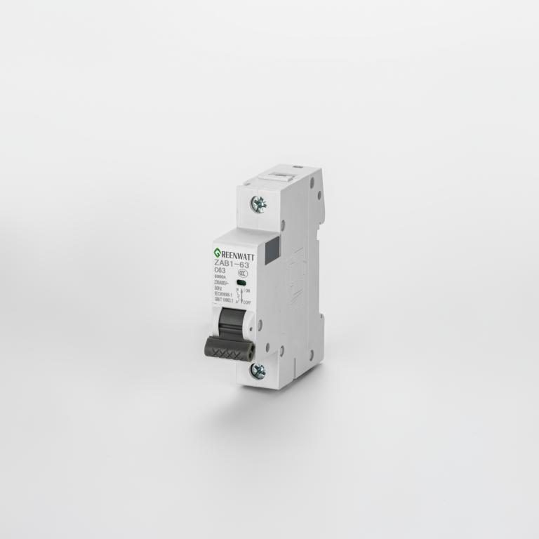
1. What Is Breaking Capacity and How Is It Defined in the Standards?
Breaking capacity is the maximum short circuit current that an AC miniature circuit breaker can interrupt without sustaining damage that would prevent it from continuing to function. It is defined in IEC 60898-1 for household and similar installations, and in IEC 60947-2 for industrial applications. The two standards use different terminology. IEC 60898-1 uses the term rated short circuit capacity (Icn). IEC 60947-2 uses the term ultimate breaking capacity (Icu) and service breaking capacity (Ics). The Icu is the maximum current the device can interrupt once, after which it may not be suitable for continued service. The Ics is the current it can interrupt repeatedly while remaining fully functional. In our factory, we test every AC miniature circuit breaker to verify both Icn and Ics values. The table below explains the key ratings and their meaning.
| Rating term | Standard | Definition | Typical value |
| Icn (rated short circuit capacity) | IEC 60898-1 | Maximum current the device can interrupt safely once | 6000A, 10000A |
| Icu (ultimate breaking capacity) | IEC 60947-2 | Maximum current the device can interrupt once | 10000A, 15000A |
| Ics (service breaking capacity) | IEC 60947-2 | Current the device can interrupt repeatedly and remain functional | 75% of Icu, 100% of Icu |
| Icm (rated short circuit making capacity) | IEC 60947-2 | Maximum peak current the device can close onto without welding | 1.5 x Icu (for AC) |
Zhejiang Dongan Electrical Co., Ltd. manufactures AC miniature circuit breaker units that are certified to both IEC 60898-1 and IEC 60947-2. Our factory tests each production batch to verify that the Icn and Ics values meet the declared specification. We also provide the Icm value for applications where the breaker may be closed onto a fault.
2. How Do You Calculate the Prospective Short Circuit Current?
The prospective short circuit current is the maximum current that would flow if a fault of negligible impedance occurred at the point of installation. It is calculated from the system voltage and the total impedance of the fault loop. The fault loop includes the utility transformer, the service conductors, the panel busbars, and the branch circuit conductors. The impedance of each component is determined by its length, cross-sectional area, and material. The calculation is performed using the formula I = V / Z, where V is the nominal voltage and Z is the total loop impedance. In practice, the calculation is often performed using software, but the designer should understand the factors that affect the result. The table below shows the typical prospective fault current at different points in a low voltage installation.
| Location in installation | Typical prospective fault current | Recommended minimum breaking capacity |
| At the utility transformer secondary terminals | 25,000 – 50,000 A | Not applicable (main breaker) |
| At the main distribution panel | 10,000 – 25,000 A | 10,000 A or 15,000 A |
| At a sub-distribution panel | 6,000 – 10,000 A | 6,000 A or 10,000 A |
| At a final branch circuit (long run) | 3,000 – 6,000 A | 6,000 A |
| At a final branch circuit (short run) | 6,000 – 10,000 A | 10,000 A |
The prospective fault current decreases as the distance from the transformer increases because the conductor impedance increases. This is why a breaker at the main panel may need a higher breaking capacity than a breaker at a remote branch panel. In our factory, we provide a fault current calculation guide with our AC miniature circuit breaker product catalog. The guide includes the impedance values for common conductor sizes and materials.
3. What Happens When the Breaking Capacity Is Exceeded?
When an AC miniature circuit breaker is subjected to a fault current that exceeds its breaking capacity, the device may fail in one of three ways. The first is contact welding. The high current melts the contact surfaces and welds them together. The breaker cannot open, and the circuit remains energized. The second is case rupture. The pressure generated by the arc inside the breaker exceeds the strength of the case, causing it to crack or explode. This can eject hot gases and molten metal, posing a risk to personnel and equipment. The third is arc flash. The arc may escape the arc chute and flash over to the adjacent phases or to ground. This can cause a phase-to-phase fault that is even more severe than the original fault. The table below shows the outcome of exceeding the breaking capacity for different device types.
| Device type | Failure mode when Icu is exceeded | Risk level | Mitigation |
| MCB (IEC 60898-1) | Contact welding or case rupture | High | Select higher Icn |
| MCCB (IEC 60947-2) | Arc flash or contact welding | High | Select higher Icu or use current limiting |
| Fuse | Rupture of the fuse body | Moderate | Select higher interrupting rating |
In our factory, we have conducted tests on AC miniature circuit breaker units at currents above their rated breaking capacity. The results confirm that the device fails as described above. This is why the breaking capacity must always exceed the prospective fault current at the point of installation.
4. How Does Breaking Capacity Affect Coordination With Upstream Devices?
Breaking capacity is not just a standalone rating. It also affects the coordination between the branch breaker and the upstream protective device. In a coordinated system, the branch breaker should clear the fault before the upstream device operates. This requires that the branch breaker has a breaking capacity that is at least equal to the prospective fault current at its terminals. If the branch breaker has a lower breaking capacity, it may fail before it can clear the fault, and the upstream device must operate to clear the fault. This may cause a larger outage than necessary. The table below shows the coordination requirements for different scenarios.
| Scenario | Branch breaker Icn | Upstream device | Coordination result |
| Branch Icn ≥ prospective fault current | 10,000 A | MCCB 25,000 A | Branch clears fault, upstream remains closed |
| Branch Icn < prospective fault current | 6,000 A | MCCB 25,000 A | Branch may fail, upstream clears fault |
| Branch Icn = prospective fault current | 10,000 A | MCCB 25,000 A | Branch clears fault, but with reduced service life |
Zhejiang Dongan Electrical Co., Ltd. provides coordination tables for our AC miniature circuit breaker units and upstream molded case circuit breakers. These tables show the maximum prospective fault current for which coordination is achieved. Our factory can also perform custom coordination studies for specific panel designs.
Frequently Asked Questions About Breaking Capacity in AC Miniature Circuit Breakers
Summary for Electrical Design Engineers
Breaking capacity is one of the most important specifications of an AC miniature circuit breaker. It determines whether the device can safely interrupt the prospective fault current at its point of installation. The selection process requires calculating the prospective fault current, comparing it to the available breaking capacity ratings, and selecting a device with an adequate margin. Coordination with upstream devices must also be considered to ensure that the branch breaker clears the fault before the upstream device operates. Zhejiang Dongan Electrical Co., Ltd. has been manufacturing AC miniature circuit breaker units for over 18 years and provides full technical support for device selection and coordination studies.
Zhejiang Dongan Electrical Co., Ltd. manufactures AC miniature circuit breaker units with Icn ratings from 4,500A to 15,000A and Icu ratings up to 25,000A. We provide coordination tables, fault current calculation guides, and custom labeling for OEM applications.